Year Introduced/Discontinued: 1997/August 2000
Power: 12.6 VDC, AC adaptor supplied
Size: 250 x 100 x 238 mm
Weight: 3.5 kg
Price: US$800, A$2000
Coverage: 0.1-30 MHz
Value Rating USA:  Europe:
This review was compiled independently. The Medium Wave Circle and Radio Netherlands has no financial connection with Japan Radio, the manufacturer of this receiver.
Japan Radio Company is starting to release more receivers for the shortwave listener. At the start of 1998 we expect to see the NRD-545 in the shops. We prefer to wait for real production models before we test that follow-up to the legendary NRD-535.
Compared to other Japanese companies such as Yaesu, Kenwood and ICOM, JRC is vast with several thousand employees. That’s because their main business is linked to marine communications and the radio amateur and short-wave radio line is a spin-off from developments in the professional world.
For the last couple of months we’ve been using and measuring an off-the-shelf version of the NRD-345 which JRC describe as designed for the “casual” short-wave listener market. This is someone who likes listening to programmes from international broadcasters but who might also dabble in some utility monitoring and some searching of the amateur radio bands. Remember, this set is not the follow-up to the NRD-535.
Essentially, a radio receiver has a pretty simple task. An external antenna hanging in the garden collects thousands of radio signals between 10 and 30000 kHz. The trick is to reject all the unwanted signals and pick out the wanted signal. The challenge is even greater when the wanted signal happens to be a very weak station coming in from another continent. Modern circuit design has come a long way in making receivers easier to tune and cope with both high power and weak stations operating on frequencies quite close to each other. At the same time, there’s a major price war on at the moment in the world of electronics, so the consumer is actually expecting more performance for much less than he or she paid ten years ago.
FIRST LOOK
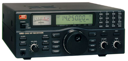
It’s a smart black-coloured box measuring 250 by 100 by 240 mm and weighing in at just under 3.5 kg. Note that the 12 V DC power supply is not built-in to the radio; it’s a separate block which plugs into the household current. You could use the NRD-345 on a car battery for mobile listening expeditions.
The front panel is dominated by a large green 7-segment back-lit liquid crystal display. It is easy to read and is part of an overall simple but rugged style that JRC have chosen. The LCD display shows the frequency with a resolution of 10 Hz. The carrier frequency is displayed regardless of the mode, so no frequency calculations or re-tuning are required. This is a receiver you can take out of the box and have working within a few minutes, because of a logical layout. There’s an excellent instruction book if you do need help.
The radio is specified from 100 kHz to 30,000 kHz, although in practice the set will tune down to 10 kHz. You can only really speak about useable performance above 30 kHz. The numerical keypad makes it possible to enter the frequency in kHz, but also in MHz. You can also enter a metre band. For instance, if you type in 120 metres, the receiver jumps to the tropical broadcast band running from 2300 – 2495 kHz, and the mode is set to AM, wide filter, 100 Hz tuning steps, AGC fast and no attenuator. If you type in: 80 m, then the receiver jumps to the 80 metre amateur band from 3500 – 3575 kHz, in LSB, narrow filter, slow AGC, 10 Hz tuning steps and no attenuator. In total, 22 bands are pre-programmed and the default values can be changed easily.
But that’s not all. There is also a tuning knob, which tunes the receiver in 5 Hz, 100 Hz, 1 kHz, 10 kHz or 1 MHz steps. Next to the tuning knob, the up- or down buttons can also be used to tune the receiver, but they don’t “speeding -up” if you press them longer, so it is easier to use the main tuning knob. The NRD-345 has a “dual VFO” system, which is in fact, as with most receivers, simply a memory. It makes it possible to jump very quickly between two frequencies. It is nice that both VFOs also store the settings of the attenuator position, the AGC, bandwidth, mode and noise blanker.
The NRD-345 has 100 memories. In addition to the frequency setting, each memory contains also setting for the mode, AGC, ATT, VFO A or B, filter and noise blanker. A lithium cell provides backup for a period of 5 to 10 years. Although the handbook gives a description how the cell has to be replaced, we think that that it is safer for most short-wave listeners to bring the receiver to the dealer, as replacement is not a simple task. It’s very easy to program, and over-write a memory channel. A programmed memory channel can be chosen with the keyboard, but also with the up-down buttons or via the tuning knob. As the NRD-345 does not have a squelch, scanning with stops at a certain signal-strength is not possible. Instead the receiver use pause scanning: it steps to a next channel at a programmable (1 to 9 sec) pause. The number of channels, which has to be scanned, can be programmed, and it is also possible to skip channels.
If you’re checking a number of frequencies of a broadcast station, note that in the scanning mode there is no squelch. So you have to reach to the front panel to stop scanning if a frequency gives good reception. We think that if you store all the frequencies of a station in ascending order, it is easier to step through the memory channels by means of the tuning knob than programming the pause scan to do the same. As you can see, we are rather skeptical about scanning on short-wave, but if you must do it, we think that you should have a squelch function.
COMPUTER CONTROL AND TIMER
The NRD-345 can also be controlled by a computer. The receiver is equipped with a RS 232C port, so no extra interface is required. Except for volume and tone, computer control of the whole receiver is possible such as frequency, mode, filter, step size, NB and ATT settings and even scanning features and the clock/timer can be controlled.
The NRD-345 also sends the settings back to the computer, including the AGC level. This offers the possibility to get a spectrum display on the screen or to stop scanning at a certain signal level. May be this would be a future option for WinRadio (see article in this edition). JRC has incorporated full instructions in the NRD-345 handbook on how to use the RS 232 control in computer programs, but does not deliver software. Those who cannot write such a program will have to wait until the authors of receiver control programs have adapted their software for the NRD-345.
The NRD-345 has a double clock, which makes it possible to toggle between local time and UTC. The clock can also be used to switch the receiver on and off at a given time. It’s understandable that JRC has left out some features to bring down the price, but we find it a pity that a switching output to control a cassette recorder has been omitted. Now you have to use a voice operated recorder to record a program automatically, or use another external timer.
MODES
The NRD-345 is equipped with detectors for AM, AM-Synchronous, USB, LSB, CW and FAX. The mode can be selected by a single pushbutton on the front panel. Fortunately the up- or down button makes it possible to step up or downwards, so it isn’t necessary to step through the whole menu. For SSB, CW and fax the same detector is used, only the BFO frequency differs: the receiver generates a tone of 800 Hz in the CW mode, which is a common value. FAX is mostly also used for data modes, such as AMTOR, SITOR and other modern systems. The NRD-345 generates a central frequency of 1900 Hz if it is tuned to the exact frequency of the station. Most computer decoders for data use however a central frequency of 1750 Hz. As the BFO frequency of the receiver cannot be adjusted, it is wise to use a decoding program which allows to change the central frequency to 1900 Hz, otherwise you always have to tune the receiver 150 Hz lower than the actual station frequency.
Like many modern receivers, the JRC NRD-345 is equipped with a synchronous detector for AM broadcast stations. But there is still a lot of confusion around synchronous detectors, so please take a few moments to read the separate article on sync detection, elsewhere in this section.
SYNCHRONOUS DETECTOR
The NRD-345 uses a synchronous detector which cannot drop out of lock, so growling sounds are avoided. But on the other hand, the receiver cannot be shifted in frequency to reduce sideband splatter. Besides that, JRC has chosen for a non-selectable sideband synchronous detector! It makes use of the full bandwidth of the chosen filter. This type of synchronous detector gives only a slight advantage during selective fading and cannot be used to reduce sideband splatter by choosing the upper- or lower sideband.
During the listening tests, the difference between standard AM and AM synchronous was hardly noticeable. Even the distortion was equal: 1.5 % in AM as well in AM synchronous. The only difference was that AM sync caused + 3 dB more volume, so it sounds by switching over a little bit more “agressive”. Although the NRD-345 is a medium cost receiver, we think that receivers in this price bracket should have a selectable sideband synchronous detector.
FILTERS
The NRD-345 is equipped with 2 IF filters, which can be chosen independent of the selected mode. For SSB/CW/FAX a Murata good quality filter, type CJF 455 K is used, with a bandwidth of 2.5 kHz at – 6 dB and less than 6 kHz at – 60 dB. This ceramic filter has become the standard in medium cost receivers. It can be used for AM reception but the audio becomes very dull. So for AM wide a low-cost ceramic filter is used, with a bandwidth of more than 4 kHz at – 6 dB and 10 kHz or less bandwidth at – 60 dB.
The NRD-345 offers the possibility to add one extra filter. JRC offers a range of 5 high quality crystal filters, from 300 Hz to 2.4 kHz bandwidth. Fine for SSB and data modes, but unfortunately there is no high quality AM broadcast filter available from JRC.
SENSITIVITY, INPUT FILTERS AND ATTENUATOR
JRC specifies the sensitivity of the NRD-345 as follows: AM: 3.2 µV in the range 100 kHz – 540 kHz, 17.8 µV from 540 kHz – 1.8 MHz and 2 µV from 1.8 – 30 MHz, all for 10 dB S+N/N with a 30% AM modulated signal. As 30% modulation depth is no longer realistic, we always measure with 60% modulation depth, which gives a sensitivity figures which are twice as large. Its clear that JRC has added an attenuator in the medium wave range to avoid overload of the receiver by strong local medium wave transmitters. For MW buffs this can be a disadvantage with the use of a short antenna. For SSB/CW the specifications are: 1 µV for 100 kHz – 540 kHz, 5.6 µV for 540 kHz – 1,8 MHz and 0.3 µV for 1.8 – 30 MHz.
Our measurements showed the following average values of our test model: all for 10 dB S+N/N, AM with 60% mod. depth, 1 kHz tone. Sensitivity figures in µV across 50 Ohms.
| Frequency | AM wide | AM narrow | AM sync | SSB/CW |
|---|---|---|---|---|
| 50 kHz -100 kHz | 5.6 | 4.7 | 5.6 | 4.1 |
| 100 kHz – 540 kHz | 1.25 | 0.83 | 1.25 | 0.81 |
| 540 kHz – 1.8 MHz | 5.8 | 3.6 | 5.8 | 3.2 |
| 1.8 MHz – 18 MHz | 0.58 | 0.42 | 0.58 | 0.33 |
| 18 MHz – 30 MHz | 0.74 | 0.48 | 0.74 | 0.41 |
These are good values. The sensitivity over a band changes a little, as the RF input filters are not flat. The NRD-345 has 8 RF input filters, which help to prevent overload from strong transmitters on other frequencies. The filters are switched with diodes. The bandwidths are as follows: a 540 kHz lowpass filter for listening under 540 kHz. A 1.8 MHz filter for listening in the medium wave band. The shortwave bands are covered with bandpass filters: 1.8 – 2.8 MHz, 2.8 MHz – 4.8 MHz, 4.8 MHz – 7.3 MHz, 7.3 MHz – 11.5 MHz, 11.5 MHz – 18.5 MHz and 18.5 MHz – 30 MHz.
The sensitivity of the receiver can be reduced by a single step attenuator. JRC has chosen for 20 dB attenuation, which reduces the sensitivity 10 times. That’s a lot. It’s good to reduce the effects of intermodulation, but makes the receiver a little bit deaf. We used a separate 10 dB attenuator during the listening tests, which reduced the sensitivity 3 times. Mostly this was enough to reduce intermodulation. Our preference is that receivers in this price class should have a 2-step attenuator: 10 and 20 dB.
SIGNAL TO NOISE RATIO AND AGC
The above sensitivity figures are for 10 dB signal + noise to noise ratio. That’s a just readable signal. More importantly, how strong does a station have to be to give 20 dB S+N/N (good intelligibility) and 30 dB S+N/N (nearly noise free). We measured the following values (on 6.51 MHz, AM 60% mod depth, 1 kHz tone, in µV over 50 ohms.
| S+N/N | AM wide | AM narrow | SSB/CW |
|---|---|---|---|
| 10 dB | 0.57 | 0.41 | 0.32 |
| 20 dB | 1.16 | 0.88 | 0.78 |
| 30 dB | 4.12 | 3.13 | 2.70 |
These values are fair. The Automatic Gain Control, AGC, is less impressive. Its purpose is to keep the volume constant, regardless the level of the received signal. Signals with a strength above 50 µV, generating 40 dB or more signal to noise ratio are constant in volume. If this is regarded as 0 dB, than a signal strength of 4 µV, (30 dB S+N/N in AM) is – 2dB, 1.16 µV (S+N/N 20 dB) gives – 6 dB volume and with a signal of 0.57 µV, generating 10 dB S+N/N, the audio level drops to -13 dB! That is too much. In practice this gives rise to the following problem. If you tune across the bands, you have set the audio volume to a comfortable level on strong stations. The audio level drops strongly if you tune to a weak station, so you have to turn up the volume control. If the next station is strong again, than it blasts out of the speaker and so on. So you have to control constantly the volume and that’s not very handy. The AGC can be switched out of operation, but that is useless because there is no RF gain control. The other settings are fast and slow, with good chosen time constants.
S-METER
The S-meter of the NRD-345 is analogue. We like this much more than the digital bar-type. In fact, the S-meter displays the AGC level, which is an indication for the strength of the received station. As explained above, the AGC of the NRD-345 cannot keep the volume constant at very low signal strengths. This is reflected in the readings of the S-meter. Besides that, there is also a difference in the reading of AM and SSB/CW signals. We obtained the following readings on our test model.
| S value | RF level in µV | Reading AM | Reading SSB |
|---|---|---|---|
| S1 | 0.2 | – | – |
| S2 | 0.4 | – | – |
| S3 | 0.8 | – | – |
| S4 | 1.6 | 3 | 1 |
| S5 | 3.2 | 4.5 | 3 |
| S6 | 6.3 | 6 | 5 |
| S7 | 12.5 | 7 | 6 |
| S8 | 25 | 9 + 10 | 8 |
| S9 | 50 | 9 + 22 | 9 + 15 |
| S9 + 10 | 158 | 9 + 32 | 9 + 30 |
| S9 + 20 | 500 | 9 + 40 | 9 + 38 |
You see that below S4 there is no reading at all, between S5 and S7 it’s OK, but at S9 and higher the meter shows much too high values. It’s a lively S-meter, but not what we expect from a company such as JRC.
PHASE NOISE
If you read test reports regularly, you will know the importance of phase-noise in the local oscillators in a receiver. A noisy oscillator can spoil the attenuation (selectivity) curves from the IF filters. In the past years, more and more receivers use a Direct Digital Synthesiser (DDS). Such a synthesiser CAN have low phase noise but a DDS synthesiser does not mean always low noise. Besides that, the second oscillator, which converts the first IF from 44.855 MHz to 455 kHz and the BFO for the product detector used in SSB, must have also low phase noise.
We have measured the overall phase-noise of the NRD-345, which uses a DDS synthesiser for the first and second oscillator.
Phase-noise measured in SSB on 3.2 MHz:
| at 5 kHz from the carrier : | 102 dBc/Hz |
| at 10 kHz from the carrier : | 110 dBc/Hz |
| at 20 kHz from the carrier : | 120 dBc/Hz |
| at 50 kHz from the carrier : | 132 dBc/Hz |
These are not more than mediocre values. Although the NRD-345 is a medium priced receiver, we have seen much better values from DDS synthesisers. The phase noise is reflected in the dynamic selectivity.
DYNAMIC SELECTIVITY
Dynamic selectivity differs from the static selectivity offered by the filters. Static selectivity is in fact the attenuation curve of the filter. Static selectivity figures are mostly much better than the dynamic selectivity, so most receiver manufactures quote these values in their brochures. But the attenuation curve of the filters does not always give a good impression of the rejection of adjacent stations. The selectivity in practice is degraded by the phase-noise of the oscillators and leakage around the filters.
Therefore our reviews give always the dynamic selectivity figures, as these give the best impression of the behaviour of a receiver. This is measured as follows: the receiver is tuned to a signal, which gives 20 dB S+N/N. This simulates the wanted station. On adjacent frequencies a signal is present, which is 60% AM modulated with a 1 kHz tone. This signal simulates an unwanted station, which has to be suppressed. For SSB, a carrier is used which simulates a SSB station with a 1 kHz tone as modulation. The signal of this adjacent station is now made so strong that the easy readable signal is degraded to moderately disturbed (14 dB S+N/N). The difference (in dB’s) in signal strength between both signals now gives the dynamic selectivity. It is a measure of how much the unwanted signal is suppressed. The measurement is repeated for different frequency distances. This measurement method closely resembles actual receiving practice. It gives a reliable impression of the receivers’ behaviour.
| Frequency Separation | AM Wide | AM Narrow | SSB/CW |
|---|---|---|---|
| 2.5 kHz | – | – | 2 dB |
| 3.5 kHz | – | 15 dB | 53 dB |
| 5kHz | 14/22 dB | 42 dB | 89 dB |
| 10kHz | 49 dB | 50 dB | 90 dB |
| 15kHz | 51 dB | 52 dB | 90 dB |
| 20kHz | 53 dB | 53 dB | 91 dB |
| 50kHz | 60 dB | 63 dB | 92 dB |
As you can see, the selectivity in SSB is good. In AM, the selectivity is good for stations up to 10 kHz away, but for larger frequency distances the attenuation of the unwanted station is not that impressive. This is caused by phase-noise, insufficient de-coupling and leakage around the filter.
At 5 kHz distance in AM wide you can see two values. A station 5 kHz higher is suppressed by 14 dB, a station 5 kHz lower is 20 dB down. The reason is that the low cost AM wide filter isn’t exactly centred at 455 kHz, a typical problem you will find with low cost filters. At larger distances the difference is only a few dB, so we noted the average value. Our conclusion is that the selectivity for a receiver in this price class is good, but not very good.
INTERMODULATION FREE DYNAMIC RANGE
In the 1997 World Radio TV Handbook we gave a whole explanation about dynamic range and intercept points. We won’t repeat that here again. The intermodulation free dynamic range is specified as the difference in level between the noise floor of the receiver and a two-tone signal, which generates a 3rd order intermodulation product equal to the noise floor. As the NRD-345 has a rather noisy synthesiser, we used 50 kHz frequency distance between the carriers of the 2-tone signal. The noise floor of the NRD-345 in SSB, measured at 3.2 MHz is – 132 dBm. With a 2-tone level of 2 x – 45 dBm the intermodulation products became as large as the noise floor: –132 dBm. This equals an intermodulation free dynamic range of 87 dB.
INTERCEPT POINTS
In the past years, we calculated the intercept points from values, whereby the intermodulation products are equal to the noise floor. Under laboratory conditions, they can just be detected. In practice however, such low level intermodulation products are not very disturbing: they are equal to the receiver noise. It is much more disturbing if the intermodulation product levels reach values from 1 or 10 µV. With most receivers, a 1 µV signal generates already a signal to noise ratio of 10 dB. This can be quite annoying or makes it impossible to receive a weak station. Therefore we also quote the IP’s for intermodulation levels of 1 and 10 µV.
| Two-tone level | Intermo- dulation product | 3rd order intercept point |
|---|---|---|
| 2 x – 45 dBm ( 2 x 1.2 mV) | – 132 dBm | – 1.5 dBm |
| 2 x – 35 dBm ( 2 x 4 mV ) | 1 µV | + 1 dBm |
| 2 x – 24 dBm (2 x 14 mV) | 10 µV | + 11 dBm |
These are not very good values, even in this medium price class. You will see that if the antenna delivers two signals of only 4 milliVolts, intermodulation products appear with a strength equal to 1 µV, which makes weak signal reception on the intermodulation frequency impossible. Remember, that a good long wire (> 20 metres) in Europe delivers 50 – 100 milliVolts in the shortwave broadcasting bands.
As the NRD-345 is equipped with input bandpass filters it is to be expected that 2nd order intermodulation figures are much better. Second order intermodulation is caused by either the sum of the difference of two frequencies. Take for instance the following example: one station is on 5950 kHz, the other on 6050. If the receiver is tuned to the sum of both transmitter frequencies: 12 MHz, the 11.5 to 18.5 bandpass filter is switched in, so both signals are suppressed.
Unfortunately the switching diodes that are used to select the required bandpass filter also cause intermodulation. We measured the following:
| Input signal (5950 and 6050 kHz) | Intermodulation product | 2nd order IP |
|---|---|---|
| 2 x – 37 dBm (2 x 3.6 mV) | – 132 dBm (noise floor) | + 58 dBm |
| 2 x – 35 dBm ( 2 x 4 mV ) | 1 µV | + 1 dBm |
| 2 x – 24 dBm ( 2 x 14.1 mV) | 1 µV | + 62 dBm |
BLOCKING
All signals picked up by the antenna are fed to the receiver input. Some stations, especially in the European short-wave broadcast bands are very strong, bringing in 20 to 100 milliVolts with a good antenna. If the receiver is tuned to another station these strong signals can overload the receiver.
This effect is called blocking. It is measured as follows: the receiver is in AM-wide tuned to a signal, which generates 20 dB S+N/N (1.16 µV) This gives a good readable signal. Another signal is generated, first at 50 kHz higher, later at 100 kHz higher, AM modulated, 60 % modulation depth, 1 kHz tone, representing an unwanted strong transmitter. The level of this signal is increased until the signal to noise ratio of the wanted transmitter is decreased from 20 to 14 dB. (from a good readable signal to moderate disturbed). The frequency distance between both stations is so large, that already maximum attenuation of the IF filter is reached, but not so large that the unwanted station do not pass he RF input bandpass filter of the receiver.
| Frequency distance | Level unwanted transmitter |
|---|---|
| 50 kHz | -45 dBm (1.2 milliVolts) |
| 100 kHz | -40 dBm (2,24 milliVolts) |
The conclusion of the figures for 2nd and 3rd order intermodulation and blocking is that the NRD-345 starts to getting into trouble as soon as the level of unwanted signals reach values above a few milliVolts. Naturally, the effects of intermodulation can be reduced with an attenuator: 10 dB attenuation drops 2nd order intermodulation products with 20 dB and 3rd order products with 30 dB, but too much attenuation will reduce the sensitivity too far. In area’s with strong signals such as Europe, we think it’s better not to use a very large antenna, preferably in combination with a step attenuator.
OTHER MEASUREMENTS AND FEATURES
At a normal audio level (100 mW into 8 ohm), the distortion of an 1 milliVolt AM modulated signal with 60 % modulation depth and a 1 kHz tone was 1.5%, in AM wide as well in AM sync. In SSB the distortion was 1.1%. This is good. The NRD-345 is equipped with 2 outputs (not affected by the tone control) with constant signal level. One is designed for a tape recorder, the other for the connection of a fax or data decoder. The recorder output gives with a 60% modulated signal a level of 45 mV, the fax output gives 1.2 V, both with a load of 1 MegaOhm. There is however one problem with these outputs. With a 60% depth, 1 kHz tone modulated signal, the recorder output delivers already a distortion of 10% and the fax output even 30%! Although 10% gives already some deterioration of the readability, for audio recording this is not the greatest problem. But some data decoders can come into trouble with a signal which is so heavily distorted.
With our test receiver, a mains adapter was delivered which converts the 230 V ac to 12 Volts DC. The receiver draws at 12 Volt approx. 0.8 Amp. But our mains adapter was not capable of delivering that much current. At the reception of a strong local medium wave station, the volume could not turned up higher than 3/4. At a higher volume the receiver produced a strong hum and the meter lighting was beating in the rhythm of speech and music. 3/4 volume is already a reasonable audio level (0.8 Watts into 8 ohm), but we think JRC should deliver a mains adapter capable of delivering more current.
The NRD-345 has also an external speaker output on the backside and a headphone output on the front panel. A stereo headphone can be used. In both cases the internal speaker is switched off. Although the terrible ticking sound of the “woodpecker” over-the-horizon radar disappeared several years, it’s nice that the NRD-345 is equipped with a noise blanker, which can suppress impulse noises. It’s a real IF blanker, working with an impulse amplifier and a delay filter in the main IF path, and not a simple audio limiter. The level whereby the blanker comes into action is adjustable on the front panel. It was quite capable to suppress the ticking sounds of an electric fence guard and other impulse noises during our listening tests.
Lastly, the antenna input of the receiver is 50 Ohms and a standard SO 239 connector is used. A switch on the backside makes it possible to switch over to a HI impedance antenna terminal for a single wire antenna and ground. This hi-impedance input makes use of a 1: 9 transformer, so the impedance is 450 ohms.
BIRDIES
Birdies are signals that are generated in the receiver itself. On a strong birdie frequency no weak signal reception is possible. They are measured as follows: the receiver is placed in a screened room, so no outside signal can reach the receiver. The antenna input is terminated with a 50 ohm dummy load. Then the receiver is tuned in USB, AGC fast, no attenuator, step size 100 Hz over the complete range from 30 kHz to 30 MHz. We noticed only birdie frequencies which are stronger than 1 µV, roughly equal to a signal which generates 10 dB S+N/N. Note that the noticed frequency gives a 1 kHz tone in USB, so the actual frequency is 1 kHz lower. We found: 2288, 9562, 9828 (S2), 13.888, 14.479, 17.220, 19.660, 22.145, 23.331, 28.688, 29.490 and a strong one (S4) on 29.599 kHz. The birdies around 17.220 and 22.145 MHz are noisy area’s of a few kHz wide. For a receiver in this price class this is a reasonable result, especially because most birdies are not very strong (around S1, approx. 1,5 to 2 µV).
Another point which has to be mentioned is that during tuning across the bands, every 200 kHz a loud click is heard. This is caused by the synthesiser.
LISTENING TESTS
We listened for many hours with the NRD-345. As antennas a 12.5 metre” long wire” with Magnetic Long wire Balun (coax lead-in to the receiver) and a T2FD antenna were used, both in combination with a step attenuator. The NRD-345 is very easy to operate and the recovered audio sounds pleasant. On the short-wave broadcast bands with strong stations we used 6 or 10 dB attenuation to reduce background intermodulation noise. With the T2FD antenna during daytime mostly no attenuation was required. The selectivity for SSB was more than sufficient and the recovered speech sounds clear and open, which is an indication for low intermodulation within the filter passband.
For AM broadcasting on short-wave the selectivity was sufficient unless we tried to listen to very weak stations adjacent to very strong stations. Than the lack of high suppression for far off stations manifests itself as sideband splatter. Switching over to AM narrow, which uses the 2.5 kHz SSB filter, helped to reduce adjacent channel interference, but not much for alternate and channels further removed from the desired channel.
The lack of higher tones in AM Narrow makes the recovered speech difficult to understand. The synchronous detector works nearly unnoticeable: by switching over from AM to AM sync we noticed less distortion during selective fading as it doesn’t fall out of lock, but it cannot help to reduce sideband splatter. Intermodulation became noticeable during our standard test: listening in the early evening hours in AM wide in the 14.1 – 14.7 and the 16.1 to 16.7 MHz segments. In these bands 2nd and 3rd order intermodulation products from the short-wave broadcasting bands can be heard in case of intermodulation. Adding 10 or 20 dB attenuation between the antenna and the receiver reduced the intermodulation products to an extent that they were not longer annoying. On higher frequencies (>20 MHz) the bands are (at press time) dead during the night, but every 5 kHz noises can be heard, from the 5 kHz spaced transmitter in the broadcasts bands. These noises are generated by the switching diodes in the bandpass filters.
CONCLUSION
The JRC NRD-345 is an extremely well built receiver, a real JRC product. It looks nice and it is very easy to operate. The specifications show performance that is really only fair, not very good, but not very bad either. It’s depending a little bit from were you live: In Europe with its strong transmitters you will notice intermodulation and overloading effects, but a step attenuator can help a lot. In other parts of the world the high sensitivity can be of advantage. We always look at the price/performance ratio.
In the Netherlands, the NRD-345 works out at US$1200, around US$200 lower than the AOR-7030. In the UK the price quoted in October 1997 was £799. For that price we think the NRD-345 is rather too expensive. In the USA though, the radio is priced in a completely different way. There it costs US$800, whereas the AOR AR7030 is 350 dollars more expensive at US$1149. In that case the NRD-345 offers fair to good value for money, being correctly priced between entry level sets such as the Lowe HF-150 and more expensive sets like the JRC NRD 535 and AOR 7030. In Australia, we noted prices in the region of AUS$1800. Value then, depends on where you happen to live!
This review first appeared on the Radio Netherlands website.