
Year Introduced: 1995
Power: 12 VDC, mains unit included
Size: 105 x 280 x 205 mm
Weight: 2.7 Kg
Price: US$1180 (Keypad US$70, Controller US$90), CAN $1800, £800
Coverage: 30 kHz – 30 MHz
Value Rating: 
This review was compiled independently. The Medium Wave Circle and Radio Netherlands has no financial connection with Lowe, the manufacturer of this receiver.
The HF-250 is the successor to the HF-225. It adds features that HF-150 and HF-250 owners were asking for: back-lit display, frequency readout to 100 Hz, 255 memory channels, more functionality in computer control, two clock timers, and tape recording switching output. In December 1996, an improved high-end version was released called the HF-250E, the “E” standing for Europa.
Options include an infra-red keypad (rather like a television remote control) and the DU250 detector board (that adds AM synchronous detection with a selectable sideband and FM). For portable operation, the option of a WA250 active whip antenna with a internally-mounted preamplifier is available.
Standard filters include 10, 7 and 4 kHz for AM, 2.2 kHz for SSB and 200 Hz for CW. The FM bandwidth with the DU250 option is 12 kHz. The user can change the default bandwidth for each mode.
Lowe Electronics of Matlock Derbyshire in the UK has a firm reputation in Europe and North America for quality shortwave receivers. Lowe Electronics have been selling shortwave receivers from decades. The move into the production area came in 1987 as a result of an absence of entry-level table-top shortwave listener sets in the UK marketplace (the Trio Kenwood R-600 had been discontinued). Early Lowe designs, such as the HF-125, looked as though they had been home-built on a kitchen table (the first ones apparently were), but the company very quickly shaped the outside casing into a unique “British” look. The same (freelance) designer has worked on the AOR AR7030, which explains the similar look.
GENERAL DESCRIPTION
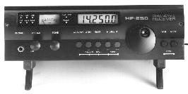
The Lowe HF-250 first appeared in the UK in late September 1995 and has since found its way into Europe and North America. The black-coloured case is made of heavy-duty extruded aluminium and is of sufficient thickness to make it a very rugged receiver, suitable for DXpeditions. The bottom plate, however, containing the four supporting feet is thinner. We began our tests using a production model with serial number 453902 that is marked on the bottom of the set. The two front feet can be clipped forward so that the receiver is tilted towards the user. We found this to be the most comfortable way to use the receiver.
The receiver is compact, just 28 by 10 by 20 centimetres and weighing in at just over 2.5 kilos. The 12V DC power supply is included in the price. It either works on 120 or 240 volts AC depending on where you buy the set, i.e. it is not dual voltage. The receiver comes with a floppy diskette (MS-DOS format) which allows you to drive most functions from a personal computer. There’s an RS-232 port on the back of the set which requires a suitable cable. Other companies have produced more sophisticated computer programs which drive the HF-250.
DESIGN DETAILS
The Lowe HF-250 is a dual-conversion super-heterodyne receiver with a first IF frequency at 45 MHz and a second IF (where the selectivity is determined) at 455 kHz. Lowe has used many proven techniques from the HF-225 and HF-150 so, from a technical point of view, the HF-250 is not a completely new receiver. On the back of the set is a sliding switch which allows you to select one of three antenna inputs. Apart from the standard 50 ohm input there is a 600 ohm unbalanced input designed for wire antennas. In the “whip antenna” position a small amplifier with high input impedance is switched in. Only use this position with a whip antenna, because the amplifier is very easily overloaded.
Directly after the input, a relay-switched 20 dB attenuator is incorporated. We felt that, for a receiver of this class, a 3-position attenuator with steps of 10, 20 and 30 dB should be offered. Personally, we believe the extra cost could be recovered from offering the whip-antenna as an option. The HF-250 uses the same mixer configuration as the Lowe HF-150: two Plessey SL 6440 high level active mixers, separated by a 15 kHz roofing filter. In the HF-250 however, 2 crystal filters are used instead of just one in the HF 150. This protects the 2nd mixer better against overloading. The greatest difference between the HF-250 and the HF-150 is that the latter has only one 30 MHz low-pass filter in front of the 1st mixer. Therefore all signals between 30 kHz and 30 MHz are fed to the first mixer, which can easily led to overloading and intermodulation.
With the HF-250 on the other hand, after the 30 MHz low-pass filter, six automatically switched filters are used before the first mixer. For longwave, there is a low-pass filter which rejects all signals above 500 kHz, the other bandpass filters are for: 0.5 to 1.7 MHz, 1.7 to 4.2 MHz, 4.2 to 11 MHz, 11 to 19 MHz and 19 to 30 MHz, preceded by a 1.7 MHz high-pass filter. Although the filters have more bandwidth than an octave, this gives a great improvement with respect to overloading effects and second order intermodulation from strong transmitters on other frequency bands.
For the IF selectivity Lowe uses the same high quality multipole ceramic filters as found in the HF-225 and HF-150, configured around a Plessey SL 6700 multi-function IF IC. The filters are partly switched in cascade. The 2.2 kHz filter is followed by the 4 kHz and 10 kHz filter. The 7 kHz filter or the 4 kHz filter is followed by the 10 kHz filter. In the 10 kHz bandwidth position only the 10 kHz filter is used.
As the other filters are by-passed and the IF stages between the filters are still in use, we recommend the use of the 10 kHz bandwidth only for high audio quality reception of strong transmitters. For CW reception the 2.2 kHz filter chain is used, but a 200 Hz bandpass filter with a centre frequency of 800 Hz is switched into the audio circuit. This gives audible reduction of adjacent CW transmitters. But it doesn’t overcome the problem that while listening to a weak CW station, the sensitivity of the receiver can be reduced by a strong CW station which lies within the 2.2 kHz bandpass of the IF filter. For that reason, it would be useful if you could switch off the AGC, and/or adjust the gain manually. This would also help if you wanted to use one of the modern DSP audio filters /noise reduction units in combination with the HF-250. The HF-250 is equipped with a noise-blanker in the audio circuit, which is permanently switched in. It responds mainly to pulse-type interference, such as ignition noise and other sparks. Overall, the Lowe HF-250 is a well designed receiver for the European price, using and improving on concepts tried and tested in earlier receivers.
FRONT PANEL
In general the Lowe receivers have an economy of buttons on the front panel. The HF-250 is no exception. That means that most buttons have a dual function and you need to spend a few hours getting the hang of some functions (like setting the timers or changing the modes).
If you connect the power supply, the radio springs to life momentarily to show the software version on the 6 digit orange-coloured LED display. The back lighting then goes off as the radio goes into stand-by mode, showing the time (including seconds). When the radio is switched on this same display is used for frequency readout (to the nearest 100 Hz, an improvement over earlier models like the HF-150). The display actually shows the frequency of the carrier in all modes.
The HF-250 comes with a number of optional extras. We would strongly recommend getting the infra-red remote control (which Lowe call the RC-250 commander). It allows you to tap in desired frequencies directly (e.g. 6-1-6-5 immediately sets the receiver to 6165 kHz). Below 3000 kHz the receiver expects you to press the ENTER key after tapping in the desired channel. Without the keypad, you have to use the UP-DOWN buttons and the large rotary tuning knob on the receiver’s front panel. We asked a couple of people to play with the set for a few hours. Each reported that they ended up using a combination of the remote control and the knobs on the front panel.
The HF-250 will store up to 255 favourite frequencies, remembering the mode as well. Lowe says the receiver will remember the channels for around 10 years! Use of the memory functions is straight forward.
FREQUENCY RANGE
The HF-250 has a frequency range of 30 kHz to 30 MHz, whereby the range from 30 to 60 kHz is not specified. Tuning steps are 8 Hz for SSB, AM synchronous (if added) and CW, 50 Hz for AM and 125 Hz for FM. Buttons for 1 MHz steps up and down are provided for larger frequency changes. There is a FAST button on the front panel to allow you to move across the dial much faster 10 kHz steps. You have to keep this button depressed with your thumb while turning the tuning knob with your the rest of the fingers on the your right hand. The tuning rate of the HF-250 changes as you spin the tuning knob faster, so the fast button is not often required. We found it handy that the tuning knob can be also used to step through the 255 memories of the HF-250, which can store frequency and as well as mode.
REMOTE CONTROL
The remote control unit is great for jumping in huge steps from one part of the dial to another (e.g. 15 MHz to longwave in one go). But the up-down buttons on the remote control have only one speed…VERY SLOW. Press the UP button with the set tuned to 6000 kHz. One minute later the receiver has reached 6015 kHz! You can MUTE the set with the remote control, but you cannot adjust the volume or tone levels from your armchair as you can on most TV remotes.
The supplied English-language instructions on programming the clock and timers are very confusing and, in our view, could do with a complete re-write. It isn’t helped by the non-standard layout of the keys. This takes some getting used to, but may well be quite handy for unattended recording, when you get used to it.
MODES
The standard HF-250 receives AM, Lower Sideband (LSB), Upper Sideband (USB), and Morse code CW. Optional boards can be installed for Narrow Band FM (NBFM) and synchronous AM (which offers optional selection of the sidebands – an improvement on some earlier Lowe models).
To change the receiving mode you first press a mode button, the current mode light starts flashing, and then by pressing the UP-DOWN keys you can sequence through the options. Once selected, you have to press the mode switch again to stop the LED blinking and return to normal tuning.
The tone control is quite effective, although on a receiver of this type may be some form of band-pass filter or notch filter would have made more practical use of the space available.
LABORATORY MEASUREMENTS
We measured the AM sensitivity of the receiver with a signal which was modulated with a 1 kHz signal to 60% modulation depth, equal to all other tests we’ve done in past years. Most broadcast transmitters currently modulate an average of 60%, even though the trend is higher with the introduction of HF-Optimod at transmitter sites. Therefore, our tests give slightly lower sensitivity figures than Lowe specifies with 70% modulation depth. But sensitivity on shortwave is not the most important specification. All signal levels are in microVolts across 50 ohms, required for 10 dB S+N/N.
SENSITIVITY
We found a sensitivity of 1.5 to 2 µVolts in the 60 kHz to 1.7 MHz range, much better than required for weak signal reception in this frequency range. Under 60 kHz, (the receiver can be tuned down to 30 kHz) the sensitivity is lower due to synthesiser noise, but with a good antenna reception of data transmitters in this range is possible.
Above 1.7 MHz the sensitivity changes from 0.76 to 1.4 µvolts, due to the ripple and differences in loss of the bandpass filters at the input. On 29.5 MHz the sensitivity of our production sample was 1.08 µVolt. The sensitivity remains nearly constant regardless of whether the 4, 7 or 10 kHz bandwidth was chosen. This is an indication that sensitivity is mainly determined by the front-end.
For SSB sensitivity we used an unmodulated signal, detuned to a 1 kHz tone. For a 12 dB sinad signal/noise ratio sensitivity figures over the 1.7 to 30 MHz lies between 0.18 to 0.27 µV. Again, these figures are good and more than sufficient. The noise floor with the 2.2 kHz bandwidth lies at – 128 dBm (0.09 µV), equalling a noise figure of 12 dB for the receiver in the range 1.7 to 30 MHz. This is a very good figure.
SIGNAL TO NOISE RATIO
Sensitivity figures give the signal required for 10 S+N/N. (signal + noise, divided by noise). At this point this signal is just intelligible. If you want to easily follow a broadcast, at least 20 dB signal to noise ratio is required. The modulation sounds clear and noise free at 30 dB or more S+N/N. We measured how much antenna signal was required to achieve a better intelligibility than with 10 dB S+N/N. With a signal of 3.1 µVolts 20 dB was achieved, for 30 dB S+N/N 9.65 µV was required in the AM mode with the 7 kHz filter. These are unweighted figures, i.e. measured over the full audio range. Measured in quasi-peak mode with a CCITT P 53A telephone filter, which gives strong attenuation under 300 Hz and above 3400 Hz, the S+N/N values improve approx. 4 dB. These are good figures.
EXCELLENT AGC
We were impressed with the action of the automatic gain control (AGC). The AGC should keep the audio at a constant level, regardless the strength of the received signals. With many low-cost receivers, the audio level drops considerably at low signal strength. This is a nuisance, because if you receive a weak station which is hard to understand, the volume drops, making the signal even more difficult to understand. You can increase the volume, but you have to reach for the control again if you start band scanning. Not so with the HF-250. The output was adjusted to 0 dB with an RF input signal of 1 milliVolts, 60% AM modulated with a 1 kHz tone. Then the level of the input signal was reduced. The audio volume was just a 0.5 dB reduced (barely noticeable) with an input signal of 0.5 µVolts. This gives a S+N/N of 6 dB, at which speech is not longer intelligible. This means that the AGC of the HF-250 keeps the audio level really at a constant level until the signal is lost in the noise. This is one of the best AGC actions we ever measured.
AUDIO
The HF-250 has a loudspeaker built into the cabinet. The speaker is mounted in a cleverly designed slot in the top, which also doubles as a carrying grip. This way of mounting gives a reduction in bass response and very high frequencies (hiss and noise). The HF-250 sounds very pleasant on music as well as speech. If you connect an external speaker to the HF 250 for long distance listening, use a communications speaker with a restricted frequency range. The audio range of the HF-250 is flat down to 40 Hz, even in the mid- position of the tone control. In the treble setting, the tone control rolls off the bass response below 300 Hz. Some shortwave listeners like this “hi-fi” approach, which is fine on stronger signals. Others may find the bass response a bit too much. It is a matter of personal taste.
With a 60% modulated AM signal (tone 1 kHz) and the 7 kHz bandwidth filter, the external speaker output delivered 2 Watt into a 5 Ohm speaker before the audio distortion rises to 10%. At standard 100 mW output level, total harmonic distortion was less than 1%, but very exact tuning to obtain minimum distortion is required. The maximum signal to noise ratio, measured wideband over the audio output was 48 dB with a RF input signal of 5 milliVolts.
We measured with a spectrum analyser the audio response of the HF-250 with the different filters. This gives an excellent indication of the combination of IF selectivity and audio response in AM. It is certainly of help, but in crowded CW bands the tone generated by the transmitters sometimes differ by not more than a few hundred Hz, and for these small tone differences the filter does not give much attenuation.
The HF-250 is equipped with a record output for the connection of a tape recorder that gives a constant output level of 320 mV at 60% modulation depth. For connection of the headphone in the front-panel jack a very sensitive type with 8 ohms impedance is required, as the headphone is fed via 220 ohms serial resistors. You can also use a modern 32 ohms types communications type. These usually have a lower bass response too.
S-METER
The set has an analogue S-meter, but in contrast to the large and prominent LCD display, the lettering on the S-meter is very small. It is difficult to read the calibration marks from 1 S point to S-9 + 60 dB. The meter is lit from the top, but it looks rather in the “budget” class compared with Japanese competition.
However, on low- and medium-cost receivers, the S-meter mostly is just an indicator. Not so with the HF-250. Despite its very small dimensions, the S-meter is very well calibrated above S3 and shows a good logarithmic response over the whole range. This is shown in figure 4. The straight line is the reading of a perfect S-meter, but you can see that the reading of the Lowe HF-250 S-meter is very good.
AM SYNCHRONOUS DETECTION
With the optional board installed, the Lowe HF-250 allows you to reduce the effects of some types of fading. Most annoying is the fact that you have to change the mode back to AM to start band-scanning again or the receiver just howls as you move in between channels. The earlier Lowe receivers were much cleverer in this respect.
We tested an off-the-shelf production sample with the optional synchronous detector already built-in. During listening tests we found that on weak signals with fading, the synchronous detector dropped out of lock and that precise tuning, exact on the carrier was required. Our measurements revealed that the synchronous detector didn’t match the specifications mentioned in the manufacturers handbook. The distortion level was too high, a very strong signal was required before the lock indicator lit-up and we had to retune the receiver 200 Hz when switching over from USB to LSB to keep it in lock.
Unsure as to whether the problem might be a fault on this particular receiver, we asked Lowe to send us a completely new second receiver, because we had some problems with the dynamic selectivity of the first receiver too. Thanks to quick reaction of Lowe Europe, a new receiver was delivered the same day. Unfortunately we discovered that the synchronous detector of the second receiver was also not working properly. It was better than the first one, and the detector kept locked even on low signal strengths, but now there was noticeable level differences between upper and lower sideband and the distortion was in the order of 10%. As we know that Lowe can make a good working synchronous detector we were surprised at these problems which we trace to alignment errors and quality control.
DYNAMIC RANGE AND INTERCEPT POINT
We measured the dynamic range and intercept point according to the CCIR recommendations for SSB marine receivers. This test uses two signals, 30 kHz apart. We tuned the Hewlett Packard 8662 A signal generators (less than – 147 dB sideband phase noise at 10 kHz from the carrier) to 10530 and 10560 kHz. Both signal generators were very well decoupled via 6 dB pads and a Wiltron combiner. The combined signal was fed via a Rohde and Schwarz DPSP precision step attenuator to the receiver, tuned first to 10500, later to 10590 kHz, on which 3rd order intermodulation products appear.
With the 2.2 kHz filter, we have to raise the level of the signals to 2 x -37 dBm, to obtain an intermodulation product equal to the noise floor of – 128 dBm. The difference of the signal level and the noise floor is 91 dB. This is the intermodulation-free dynamic range of the HF-250. Also the third order intercept point is now determined: (91/2) + (-37 dBm) = + 8.5 dBm. For the price class of this receiver in Europe these are certainly very good figures, although not sufficient to use the HF-250 with a very large antenna without the use of an attenuator. That is the reason why we’d like to see a multistep attenuator instead of the single 20 dB position.
A signal of – 37 dBm equals 3.16 mVolts. This is indicated on the Lowe S- meter as S9 + 30 dB. If two or more signals higher in level than S9 + 30 dB fall within the passband of one of the 6 RF input filters (so they are together fed to the first mixer), 3rd order intermodulation products can disturb reception of very weak stations.
DYNAMIC SELECTIVITY
There are two kinds of selectivity. The static selectivity is the attenuation curve of the IF filters. Lowe uses good quality multi-pole IF filters. The 2.2 kHz SSB filter has a – 6 dB bandwidth of 2.3 kHz and the bandwidth at 60 dB (1000 times) attenuation is just 3.4 kHz. For the 4 kHz filter these values are: 5.9 and 9.8 kHz, for the 7 kHz filter 8.8 and 12.9 and for the 10 kHz filter they are 10.5 and 21.5 kHz. These are nice values, and the bandwidth remains tight up to 80 dB attenuation. But this is not the whole story. In practice, these static selectivity curves are not as good in any receiver. There is always some signal leakage around the filter, perhaps caused by the printed circuit board or leakage via the power supply connections in the amplifier stages in between the filters.
The main problem however is noise generated by the main-oscillator, the synthesiser. In short: if the noise level of the synthesiser is too high, this noise is mixed back into the passband of the IF filter. This is called reciprocal mixing. The result is that high attenuation of unwanted signals is no longer achieved.
The CCIR measuring protocol for marine shortwave receivers gives rules for the measurement of the dynamic selectivity, also called RF protection ratio. This measurement protocol gives selectivity values in which all the effects of synthesiser noise and leakage are incorporated. So, dynamic selectivity gives a real impression of the selectivity in practical use.
All the receivers tested by Radio Netherlands in the past years are measured for dynamic selectivity. For the measurement, the receiver is tuned to the signal of a low- sideband noise signal generator, AM modulated, 60% modulation depth with a 1 kHz tone. The level of this signal is adjusted, until the receiver gives 20 dB S+N/N, which is an easily intelligible signal. This is called the wanted signal. For the HF-250 this level was 3.1 µVolts. At the same time, the signal of a second generator, also modulated with a 1 kHz tone with 60% modulation depth, is fed to the receiver. Both signal generators are properly decoupled, so they do not influence each other. The second generator is first tuned to a higher frequency, in steps of 0.1 kHz up to 30 kHz away from the frequency tuned in on the HF-250. Later the second generator is tuned to lower frequencies. It is clear, that as soon as the signal of the second generator falls outside the passband of the chosen filter in the receiver, the signal of the “interference” generator can be higher than that of the wanted signal. The level of the interfering signal is then raised, until the signal to noise ratio of the wanted signal drops to 14 dB. This is an intelligible signal, but slightly disturbed by the unwanted signal.
This is a good practical test. The receiver is tuned to an easily intelligible signal. For the HF-250 this is approx. a S3 signal. The dynamic selectivity now gives (in dB’s) how much stronger an interfering signal must be before a wanted signal suffers slight disturbance. This situation can be found all over the broadcasting bands.
Our first production sample of the HF-250 had a level of synthesiser noise which was far too high, with as result that selectivity was bad. The second example of the receiver which we purchased didn’t have this problem and we measured a synthesiser noise of – 128 dB/Hz at a distance of 20 kHz. This is a good value for a receiver in this price class. In the dynamic selectivity curve you can see that just next to the passband of the chosen filter in the receiver, the signal can be up to approx. 65 dB (1780 x) stronger. In fact it is the attenuation curve of the filter. But on larger frequency distances the attenuation curve flattens and the level of the unwanted signals cannot rise much more. This deterioration of the attenuation curve of the filter in the receiver is caused by sideband noise, filter leakage and overloading. Compared to other receivers is this European price class, the dynamic selectivity of the Lowe HF-250 is good. The AOR AR7030, however, has a better figure.
OVERLOADING
If you listen to an easily intelligible signal, signals of unwanted transmitters higher or lower in frequency cannot be of unlimited strength. If they become too strong, the receiver cannot handle them any longer without disturbing the signal of the wanted station. You’ll notice this if you listen to amateur radio stations in the 7 to 7.1 MHz band, while the antenna delivers at the same time (in Europe) extremely strong signals of the 41 metre broadcast band (7.1 to 7.3 MHz)
To see what kind of signal level the receiver can handle before the wanted station is disturbed, we use the same measurement method as for the dynamic selectivity, but now the unwanted signals are placed on 100 and 200 kHz above and below the wanted signal frequency. Independent of the selected filter and mode, we found levels of 74 dB and 77 dB above the 20 dB S+N/N sensitivity. This equals a signal level of respectively: 14.7 mV and 20.8 mV. These are very strong signals, which appear on the S-meter as roughly S9 + 50 dB readings. In Europe with large antennas these strong signals are common on long and medium wave, the 41 and 49 metre band. The overload point is not fixed, because the AGC circuit is placed in between the first and second mixer. It has to be mentioned that as soon as signal levels rise above 8 mV (S9 + 40 dB) the HF-250 begins to produce birdies (whistles) and noise on a number of frequencies around this strong signal. Therefore the use of the attenuator is required.
BIRDIES
Birdies are “ghost” signals such as carriers, whistles and noises produced by the receiver itself. If the birdie is strong, weak signal reception on that frequency is not possible and even moderately strong signals can be disturbed. All receivers produce birdies, but they should be so low in level, that they disappear in the atmospheric noise when an antenna is connected. For this measurement the antenna input of the receiver is terminated with a 50 ohm dummy-load and the receiver is placed inside a grounded metal cabinet (Faraday cage), to prevent reception by direct radiation. Then the receiver in USB mode is slowly tuned from 60 kHz to 30 MHz, during which any birdie frequencies and their equivalent signal strength is noted.
Here we come to a firm point of criticism. The second HF-250 receiver was better than the first one, but both receivers produce hundreds of birdies. Lucky enough, most of them are so low in level, that they do disappear in the noise when an antenna is connected, but we found a lot of birdies with a high level, some of them with a equivalent signal strength of up to S6 on the S- meter. To give you an idea we note here some of them with the S-meter reading of S2 or higher. Noted is the frequency which produce a 1 kHz tone in USB, the actual frequency is 1 kHz higher. 2158 (s2), 2161 (s2), 2879 (s2), 3599 (s2), 4859 (s3), 5041.5 (s3), 5759 (s2), 10619 (s2), 10800 (s2), 11519 (S4), 12059 (s2), 13499 (s3), 14399 (s5), 14543 (s2) 14847.5 (s6), 14939 (s3) 16318.5 (s3), 16379 (s4), 17278 (s5), 17819 (s2) and so on. We think that for a receiver in this price class the number of birdies and their level is much too high, and we think Lowe should do something about it in future.
SQUELCH
It seems strange that the squelch level control is on the back of the receiver! If you mount the receiver in a rack that makes Narrow Band FM mode rather complicated to use!
GENERAL CONCLUSIONS
The Lowe HF-250 is clearly the successor to the HF-225 Europa and, in most respects, is an improvement on the budget HF-150 model. There are some tuning quirks which take some getting used to. The radio has excellent fidelity and it well-suited to shortwave programme listening.
From a technical point of view we think that the Lowe HF-250 is a good performer and on some specifications even an excellent receiver for the price in Europe. We haven’t yet tested the HF-250E, which has better specifications than the HF-250. This nicely fills the gap between the Lowe HF-150 and the more expensive receivers such as the Icom R 72 and the Kenwood R 5000. We would like to see less birdies, and a multi-position attenuator fitted as standard.
In Europe, demand for the receiver has been good. The standard HF-250 is advertised in most magazines for around £785 in the UK where is it priced under the Drake R8-series. There is considerable competition from the AOR AR7030 that is priced at £799 in the UK and, in some respects, has better specifications for DXing. We advise you to check both sets side-by-side.
In the rest of Europe, the HF-250 offers good-excellent value. In the USA, however, the exchange rate and import duty means the basic HF-250 is priced at US$1199, the basic set plus the remote control is US$1249, and with the sync option plus remote the price is US$1349 which probably means it will only appeal to collectors. Lowe has to re-consider its pricing policy in this region if the new HF-250 is to break into the North American market alongside other sets like the Drake R8-series.
THE HF-250E
A “Europa” version of the HF-250 started shipping in December 1996. Lowe tells us that the price is same as the HF250, and the feature set is equivalent to the HF-225E Europa. We have not yet tested this new model.
This review first appeared on the Radio Netherlands website.