
Note: In late 1997 AOR UK introduced the AR7030 PLUS. Additional features include increased balance of the mixer; high tolerance, low noise components; 400 memories with multi-timers; improved front end performance; and a ceramic metal cased 4 kHz (displayed) AM filter fitted as standard (typical bandwidths: 2.2kHz, 4.0 kHz, 5.3kHz 9.5kHz). The price is US$1269. We have not tested the AR7030 PLUS.
Year Introduced: 1996
Power: Mains
Size: 238 x 93 x 227 mm
Weight: 2.2 kg
Price Less options: US$1150, CAN$1875, £730, A$2150
Coverage: 0-32 MHz
Value Rating star 
RADIO NETHERLANDS RECEIVER TEST REVIEW: FULL REVIEW
This is an independent review. The Medium Wave Circle and Radio Netherlands has no financial connection with AOR, the manufacturer of the AR-7030. In December 1996, the World Radio TV Handbook gave this receiver an award: Best Table Top Receiver 1996/7: AOR AR-7030. “Especially in Europe, the price-performance offered by this new set is outstanding. We’re impressed by AOR’s after sales service.”
Reviewers: Jonathan Marks, Willem Bos & Diana Janssen.
INTRODUCTION
First announced in late 1995, early production models appeared at the start of 1996 and were sent to dealers and a few reviewers. Quantity production really started in the spring of 1996. The receiver company is Japanese, but this particular model is designed and built in the UK. Design engineer John Thorpe, who designed most of the HF series of receivers for the Lowe company, went freelance and signed a deal with AOR to design the 7030.
Receiver technology is rising to new heights. New insights, better integrated circuits and production methods have led to two philosophies. Some manufacturers have chosen for complex receivers with digital signal processing and a lot of features and facilities. Others, especially British manufacturers, produce receivers without frills, but offering very high quality receivers for a reasonable price. The AR7030 falls into this latter class. AOR manufacture the receiver at their base in Derbyshire, in the UK. The radio offers excellent performance in the price class, but we suggest you check if you like the way of operating the receiver before you decide to buy one.
GENERAL DESCRIPTION
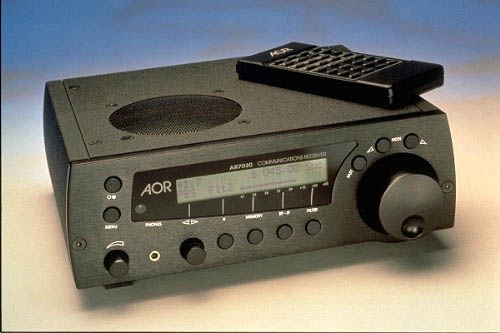
The AR7030 is a small and very compact communications receiver measuring 238 x 93 x 227 mm. It weighs just 2.2 kg. The CNC machined aluminium cabinet is beautifully made and of very high quality. The receiver comes with a small 32 key infrared remote control, which is essential for full operation of the AR7030. An AC mains adapter, which delivers 15 Volts DC is also included. The power supply runs warm so should get enough ventilation. The receiver can be operated from a 12 Volts DC source such as a car battery, but the performance is degraded with supply voltages lower than 15 Volts DC.
FREQUENCY COVERAGE AND TUNING
The frequency coverage of the AR7030 is 0 to 32 MHz. It really tunes down to 0 Hz, but coupling capacitors and IF filters only makes reception first possible above a few kHz. That’s sufficient, because transmission of radio waves start at 9 kHz. The AR7030 has the following antenna inputs: 50 Ohms unbalanced with a SO 239 connector, which can be switched over to high impedance for a whip antenna (with reduced RF performance) and a 600 Ohms unbalanced clamp type input for wire antennas. The receiver can be tuned with 2.655 Hz steps in the CW/SSB/DATA modes, and 10.62 Hz steps in AM and FM narrow modes. Tuning rate from the spin-wheel tuning knob is 1 kHz per revolution, increasing with rapid rotation. Fast tuning increases the tuning rate 256 times. Tuning steps in any size from 2,7 to 50 kHz can be selected only with the infrared remote controller, which makes it also possible to give direct numeric frequency entries within 1,4 Hz. The rubber pushbuttons on the controller are rather small, but operation is easy as it is possible to enter frequencies in kHz as well as MHz. The contrast adjustable display shows the correct frequency, i.e to within 10 Hz resolution, In the SSB mode, the frequency of the suppressed carrier is shown. It is unlikely you would use the remote control from any distance since the figures in the display are too small to see from the other side of the room. You have to point the remote accurately before the radio reacts.
MODES
The modes covered are AM, AM synchronous, USB, LSB, CW, DATA and FM Narrow. The receiver is equipped with passband tuning: the IF filter passband can be shifted 4,2 kHz up- and downwards in 100 Hz or 33 Hz steps with respect to the tuning frequency. This is also used to select the desired sideband in the AM sync mode. Some other receivers make it possible to choose directly between upper and lower sideband in AM sync. This is handy when listening to transatlantic medium wave stations. On the other hand when the AM sync detector on the AR7030 is locked, the passband shift can be used to listen to the upper or lower sideband. You have to twiddle with some pushbuttons and a rotary control, but this continuously variable system has the advantage that you can adjust the passband so as reduce adjacent channel interference to a minimum. The AM sync detector on the AR7030 is unusual in that it is self-tuning. Normally a receiver with an AM sync detector has to be adjusted with nearly the same accuracy as listening in SSB to an AM modulated station. With the AR7030 you can tune within + 2 or – 5 kHz to the station in AM, and when you switch over to AM sync, the receiver tunes locks onto the exact carrier frequency of the received station and locks onto it. The process can take a few seconds but once locked it won’t spring out of sync, riding through the deepest of fades.
MEMORIES
The AR7030 has 100 memories. In each memory channel information about the frequency, bandwidth, mode, passband shift – or BFO setting, squelch and scan include/exclude can be stored. The memories can be scanned with variable hold- and delay time between any two selected channels (each adjustable from 0 to 100). Memories in between the upper and lower channel, can be in- or excluded by hand. Two VFO’s are provided. Each VFO holds independent settings of frequency, mode, bandwidth, IF gain, passband tuning or BFO, RF attenuator or gain, AGC speed, volume, tone, squelch setting, scan mode and scan delay time and hold. A nice feature is that the receiver can automatically switch between the VFO’s. This gives the same possibility as the priority channel on popular scanners: looking at adjustable intervals to a particular frequency to see if there is any activity. This feature is very handy for utility monitors, because some data stations can give an idle signal for hours. For some people, 100 memories may be on the low side. We tested one of these receivers alongside an NRD-535D at a DX camp in Northern Finland. When scanning for North American medium wave signals, we couldn’t store all the AM channels in one go.
SELECTIVITY
The AR7030 is equipped with 4 IF filters for main selectivity. These turn out to be a good quality 2.2 kHz ceramic filter for SSB/CW Data and three low cost filters for AM with 10 kHz, 5.5 kHz and 7 kHz bandwidth. The PCB has room for 2 more filters and is prepared for the use of either low cost or high quality ceramic or mechanical filters. Several filters, including the Collins mechanical filters with 500 Hz, 2,5 kHz, 4 kHz and 6 kHz bandwidth are offered as option by AOR and also by the US firm of KIWA Electronics.
It is well known that especially low cost ceramic filters have large frequency tolerances. For receiver designers this is a problem because BFO and carrier settings are mostly fixed. This will lead to unequal adjacent signal suppression and distortion in AM or shifted passband in SSB/CW. Thanks to the use of synthesisers for the mixing signals and sophisticated software, this problem has solved on the AR7030. It has a built-in filter calibration routine. After the first start-up or replacement of a filter, the program measures the filter bandwidth at – 6 and – 20 dB, identifies the centre frequency, sets the correct carrier insertion frequency, shows the – 6 dB bandwidth on the display and orders the filters in ascending bandwidths. The displayed bandwidth is therefore not a pre-programmed value, but the real bandwidth which differs from receiver to receiver. Our test receiver showed values of 2,1 kHz, 5,4 kHz, 6,4 kHz and 9,5 kHz. For special purposes the IF at 455 kHz is available at the AUX connector with a level of 22 mV at 50 Ohms.
Except for the 1,7 MHz high- and lowpass filters, the AR7030 has no RF selectivity. With a large antenna, signal levels in Europe on the 6, 7 and 9 MHz broadcast bands can easily reach values up to 100 milliVolts or more and this will lead to overloading and intermodulation. Fortunately the AR7030 is equipped with relay switched attenuators which give 0, – 10, -20, -30 and – 40 dB attenuation, so the signal level can be brought down in steps to just under the level at intermodulation sets in. With very strong signals, the attenuator is switched in automatically, to reduce the sensitivity.
AUTOMATIC GAIN CONTROL
The “hang” type Automatic Gain Control (AGC) is derived from a mean detector in the AM mode, and from a peak detector in the SSB/CW modes. This gives an attack time of approx. 8 msec in AM and 4 msec in SSB. The AGC decay time can be selected: fast (approx. 0,7 sec), Medium (approx. 1,2 sec) and slow (approx. 2 sec). We found these values to be well chosen. With certain type of signals it is better to switch off the AGC (fortunately this is possible) and adjust the receiver gain by hand to a fixed value. The IF gain can be adjusted in steps from 3 to 99%.
The AR7030 is not equipped with a noise blanker. The full audio path is stereo, up until the mono loudspeaker, and delivers 2 Watts to the external speaker output. Treble and bass can be adjusted separately in steps: +/- 8 dB at 2 kHz in 2 dB steps for treble, +/- 9 dB at 200 Hz in 1 dB steps for bass. The receiver has an output for an external loudspeaker and an output for 32 Ohm headphones. We connected the radio up to a hi-fi set and enjoyed excellent fidelity over the system.
Two constant voltage (independent of the volume control) outputs are available for modems and decoders etc. Each output can be adjusted in level from 0 to 800 mV generated by a signal with 70% modulation depth. A 24 hour clock is included and the time is displayed when the receiver is switched off. The clock can be used to switch the receiver on, and run, or sleeptime can be set up to 4 hours. The built-in squelch driven relay can be used to switch-in a tape recorder for the chosen runtime. Nearly all functions of the AR7030 can be controlled via the RS 232 computer control socket on the rear panel of the receiver.
SOFTWARE CONTROL
There is control software available for the AOR receiver developed by Simon Collings, an independent software developer and radio communications consultant. The package for based computers is available through AOR and dealers. The AOR control software for the AR7030 is called DATA MASTER and comprises RS-232 control applications for the receiver, an AOR badged version of the MUFsight propagation prediction utility and the AOR Data Base Toolkit. The software is copy-protected and well documented; a manual of around 100 pages accompanies the set of distribution disks, just under 10M bytes of programs and data. The software is clear and simple to use, letting you configure memory data, tune the radio from a realistic front panel displays and import transmitter data from the AOR Data Base Toolkit overlaying it onto a world map for point and click tuning. The program uses an RS-232 serial port to communicate with the radio. We found the database function to be very useful and the “virtual” AR-7030 has more knobs on the front panel than the real device. We found it useful to be able to send or retrieve memory data from the radio and print it out. The system requires a Pentium P60 or above, 8M bytes of memory or more (16M bytes recommended) and you need to be using Microsoft® Windows 3.1 (or higher) or Microsoft ® Windows for Workgroups 3.1 (or higher) running in enhanced mode; Windows® 95 . Windows NT is not currently supported. At press time we were not aware of AOR software for the Apple Macintosh. It is essential to keep the antenna well away from the computer and use screened cable as a lead-in to the AOR. We discovered that background noise was reduced if the computer was connected to a different power socket.
OPERATING THE RECEIVER
The front panel is deceptively simple, sporting just 9 pushbuttons, two rotary controls and a large tuning knob with a dimple in the face for serious tuning. New with respect to other receivers is that all keys and adjustments are under software control: no analogue potentiometers or switches that gradually cause crackling and noise after a few years of heavy use. A backlit 2 row, 24 character LCD display gives all the necessary information about the controls, but not in one single view. The display is easy to read from most angles, even if you tilt the set towards you by unfolding the foot at the front.
The receiver is controlled via menus in a tree structure. To adjust some controls, you have to push one or more buttons, before the display shows the desired control. The upper row shows data such as tuning frequency A and/or B, memory contents, mode, volume setting in %, IF gain in %, delay time, AGC, passband and BFO settings and so on, depending on the chosen menu. The lower row indicates primarily the functions of the rotary controls and the softkeys in a menu tree. In the right menu setting you can also see a large, 70 bar S-meter. Apart from individual control, it is also possible to store three different set-up menus, for instance for AM broadcast listening, SSB reception and for other type of stations, for instance data or FM on the 10 or 11 metre band. Each menu stores the setting for filter, AGC, RF gain, mode, and so on. It’s a handy way to start with when switching on, but if you want to change something, you have to cycle through the menu trees again.
Whether you like this method of operating a receiver is very much a matter of personal taste. We gave this set to five different users and got either very positive or very negative comments back, nothing in between, Of course it’s a matter of taste, but we find this way of operation rather clumsy, at least at first. The rotary knob under the display for instance, acts as a control for treble and bass, squelch level, passband setting in the AM sync mode, delay time when switching between both VFO’s or during scanning, BFO setting in the CW or data mode and acts as memory channel selector, all depending of the chosen branch in the menu structure. You have to look what the current control function is, think how you can reach the wanted control function, push on one or more buttons, after which you can finally correct the setting. It true that you get used to it and that a number of controls can be operated from the infrared controller without first choosing the right menu tree. We would have preferred a more straight forward approach with a pushbutton for every important function. On the other hand the very good price/performance ratio of the AR7030 is only achievable thanks to this total software control. A large cabinet with a front panel full of pushbuttons and rotary controls is much more costly.
SOME TECHNICAL DETAILS
The AR7030 is a double super with IF’s at 45 MHz and 455 kHz. A DDS synthesiser encapsulated in a dyecast aluminium box, provides an extremely low phase noise local oscillator with frequency steps of 2,7 Hz (10.6 Hz in AM and FMn mode). A temperature compensated X-tal oscillator is used to achieve the excellent stability of + or – 1 Hz per MHz at normal room temperature. The receiver is wideband, without band selecting filters or a pre-selector, but it has a 1,7 MHz high pass filter which rejects all long- and medium wave stations while listening on shortwave. For listening on long and medium wave a 1,7 MHz loupes filter rejects all shortwave stations.
A nice detail is that the attenuator switching directly after the antenna input, as well as all other switching before the first mixer, is done with relays instead of cheap, intermodulation-prone diodes. A wideband 10 dB gain amplifier build around a 2N3866 transistor can be switched in if the receiver is used with a low efficiency (short) antenna. For those who are forced to use a whip antenna, an impedance inverter with a J310 fet is available, but -as in the Lowe receivers- it can generate 2nd and 3rd order intermodulation. The first mixer is a quad fet switching type mixer (SD 5400) and after the 15 kHz wide roofing X-tal filter at 45 MHz, the well known Plessey SL 6440 is used as high level second mixer.
Four IF filters are standard, and there is room for two more filters which are available as option. For SSB/CW/DATA a good quality ceramic Murata CFJ 455 k filter with a bandwidth of 2.2 kHz is used. All other filters are low cost 455 HT ceramic block types. It is easy to replace the 2.2 , 5.5 and 7 kHz filters by higher quality filters as space for Murata or Collins filters is provided. The 10 kHz filter cannot be replaced. The IF processor is a TDA 1572, followed again by low-cost block filters (not replaceable), a NE 612 as AM/product detector and a Motorola MC 3357 as FM detector. A DDS/PLL synthesiser is used to generate the signal for the product detector and the latter is also used in the AM sync mode.
The receiver is controlled by a 89C52 microprocessor with EEPROM storage and a rechargeable battery-backed RAM memory for the clock and filter calibration data. The battery is charged by the receiver and doesn’t have to be replaced. It holds its charge for a long time if the receiver is not connected to the mains. The whole circuitry of the AR7030 is contained on one, large epoxy printed circuit board, mainly filled with miniature size SMD components. It is a well-laid out and nicely designed board without modifications. Only the fearless will attempt to fiddle themselves, partly because no schematic diagrams are incorporated in the users handbook. It has to be said though that AOR are prompt and helpful with any questions about the receiver… one of the best after sales services in the world.
MEASUREMENTS
It is important that measurements by reviewers are carried out on the same way and with the same type of signals, otherwise it is impossible to compare measurement results. Therefore we have not followed the use of deeper modulated AM signals in order to get higher 10 S+N/N sensitivity figures, but used a 60% modulated signal as in all our earlier tests.
SENSITIVITY
The sensitivity figures are fine. Remember that the atmospheric- and man-made noise is very high on shortwave and sensitivity is less important. If a low efficiency antenna is used, the + 10 dB preamplifier can be used, but be careful because intermodulation products become 30 dB stronger than in the 0 dB position. Due to the noise figures of the amplifier and the receiver, the pre-amp does not give 3,16 times (10 dB) more sensitivity. It improves the sensitivity approximately 2 times in the range 20 kHz to 7 MHz, and roughly 2,5 times in the upper part of the shortwave bands.
SIGNAL-NOISE RATIO AND NOISE FLOOR
The sensitivity figures are very good. Even with relatively small signals (S5 in AM and S4 in SSB) good intelligibility is achieved. Maximum signal/noise ratio in AM was an excellent 50 dB with a 4 mV signal. The minimum discernible signal (noise floor) in SSB was – 122 dBm (0.18 µV) with RF gain 0 dB, with the preamp on (RF gain + 10 dB) the noise floor was – 129 dBm (0.08 µV).
PHASE NOISE
The sideband phase noise of the local oscillators in a receiver is a very important specification. When the oscillator signals are noisy, as in many synthesised oscillators, adjacent stations are mixed back into the passband of the receiver by reciprocal mixing. The result is that the dynamic range, dynamic selectivity and suppression of stations at a large frequency distance is reduced. A receiver with a noisy synthesiser sounds noisy and “unsettled”. The phase sideband noise is expressed in dB’s with respect to the carrier, in 1 Hz bandwidth (dBc/Hz). Medium- and high class amateur receivers show an average value of sideband noise in the order of -135 dBc/Hz at 50 kHz frequency distance of the carrier. The AR7030 is equipped with a DDS synthesiser with an exceptionally low sideband noise. We measured the following values:
PHASE SIDEBAND NOISE
at 5 kHz distance : – 123 dBc/Hz
at 10 kHz distance : – 133 dBc/Hz
at 20 kHz distance : – 142 dBc/Hz
at 50 kHz distance : – 153 dBc/Hz
These are the best figures we have ever measured, even with highest class receivers. DDS synthesisers have low sideband noise, but can generate spurious signals. The AR7030 DDS synthesiser is also very good on this subject, spurs are only a fraction higher than the noise.
It means that the AR7030 scores on this specification approx. 10 times better than the average medium class receiver. In practice this low sideband noise makes that the receiver sounds very quiet, clear and open, even with low level signals. Another advantage of this low noise is that even with the low-cost AM filters, the dynamic selectivity is high. In receivers with noisier synthesisers the dynamic selectivity is poorer than the static selectivity (attenuation curve of the filters and max. suppression of signals outside the passband). This means also, that replacement of the low cost filters by high quality mechanical filters (certainly a 4 kHz Collins filter if you are a broadcast listener) is to be recommended. Thanks to the low sideband noise, almost the full selectivity offered by the better filter is really obtained.
DYNAMIC SELECTIVITY
As mentioned above, dynamic selectivity differs from the static selectivity offered by the filters. Static selectivity is in fact the attenuation curve of the filter. Static selectivity figures are mostly much better than the dynamic selectivity, so most receiver manufactures give only these values. But the attenuation curve of the filters does not always give a good impression of the rejection of adjacent stations in practice.
At Radio Netherlands, we always give the dynamic selectivity figures, as these give the best impression of the behaviour of a receiver. This is measured as follows: the receiver is tuned to a signal which gives 20 dB S+N/N. This simulates the wanted station. On adjacent frequencies a signal is added, which is 60% AM modulated with a 1 kHz tone. This signal simulates an unwanted station which needs to be suppressed. For SSB, a carrier is used which simulates a SSB station with a 1 kHz tone as modulation. The signal of this adjacent station is now made so strong, that the signal+noise to noise ratio of the wanted station is degraded to 14 dB. This means that the easily readable signal is degraded to moderately disturbed. The difference (in dB’s) in signal strength between both signals now gives the dynamic selectivity and is a measure of how much the unwanted signal is suppressed. The measurement is repeated at different frequency distances. This measurement method simulates receiving conditions in practice and gives therefore a good feel for the behaviour of the receiver.
DYNAMIC SELECTIVITY
| Frequency distance | AM 5,4 | AM 6,4 | AM 9,5 | SSB/CW 2,1 |
|---|---|---|---|---|
| 3 kHz | 48 dB | |||
| 4 kHz | 62 dB | |||
| 5 kHz | 22 dB | 1 dB | 89 dB | |
| 10 kHz | 65 dB | 48 dB | 30 dB | 99 dB |
| 15 kHz | 73 dB | 63 dB | 57 dB | 110 dB |
| 50 kHz | 82 dB | 74 dB | 70 dB | 124 dB |
Even with the used low cost AM filters, these dynamic selectivity values are very good. We believe, and that was also our experience in practice, that the difference between the 5,4 and 6,4 kHz filter is too small. The 6,4 and 9,5 kHz filters are fine for listening on medium wave, as the channel spacing on this band is 9 kHz (Europe) or 10 kHz (USA). On the shortwave bands the channel spacing is 5 kHz. The 5,4 kHz filter gives sufficient rejection for stations on 10 kHz and more frequency distance, but for DX reception we advise to buy a 4 kHz AM filter if you can afford it. The 2,1 kHz filter is excellent for SSB, but if you are an experienced data listener, placement of the optional 1 kHz data filter is certainly recommended.
DYNAMIC RANGE AND INTERCEPT POINTS
In our opinion, customers always want to compare specification and you can only do this is people are using the same measurement techniques. There is an article elsewhere on this web site that goes into more detail. Over the last 10 years, we used a measurement method whereby the generated intermodulation product is equal to the noise floor of the receiver. After correspondence with the ARRL lab in Newington USA, Günter Schwarzbeck (DL1BU, the world renowned German receiver tester) and others, we decided to add measuring results with IM levels equal to 1 µV and 10 µV. This gives a more complete view on the behaviour of receivers with different levels of strong signals.
It gives you also the possibility to put sets side by side. If you compare receivers elsewhere on the web, look at the IP3 for an IM product equal to the noise floor. If you want to know which levels delivered by the antenna produce a clearly detectable, or really disturbing IM product, look at the signal levels which produce respectively an IM product with 1 µV or 10 µV level. The dynamic range is measured, not calculated, from the highest intercept point with the noise floor as reference.
DYNAMIC RANGE AND THIRD ORDER INTERCEPT POINT
Measurements are carried out as follows: 2 ultra lownoise (< -158 dBc/Hz phasenoise on 10 kHz) Xtal oscillators are combined in such away, that they do not influence each other. Frequencies are 3,2 and 3,25 MHz (50 kHz spacing), signal levels are equal on exactly + 6 dBm. Via a fixed attenuator of 6 dB, which ensures that receiver input impedance cannot influence the combiner, followed by a precision step attenuator, the signal is fed to the receiver. First, the generator on 3,2 MHz is switched off. The receiver is tuned in USB to 3,249 kHz, in order to produce a 1 kHz tone. The audio output of the receiver is via a CCITT psofometric filter connected to a Fluke 8922A true RMS dB & Voltmeter. Other receiver data: RF gain 0 dB, IF gain 99%, volume 65%, USB 2,1 kHz filter, AGC on medium decay, bass and treble 0 dB. Now the noise floor is determined by adjusting the input signal in such a way, that the voltmeter shows a 3 dB rise in true RMS level. The level of the input signal is than equal to noise floor and represents the minimum discernible signal. Next the S-meter reading is noted with 1 µV and a 10 µV signals. Now the generator on 3,2 MHz is also switched on. IM products appear on 3,105 and 3,3 MHz. The receiver is tuned to 3,299 MHz, in order to produce a 1 kHz tone on the 3,3 MHz IM product. The level of the combined 2-tone signal is now adjusted in such a way, that the IM product gives a 3 dB rise of the noise floor. The difference in level, expressed in dB’s, between one carrier of the 2-tone signal and the noise floor is the dynamic range of the receiver. From these values also the 3rd order intercept point can be calculated. This IP 3 figure can be compared to our earlier tests and those of many other reviewers. Then the level of the 2-tone signal is increased until the IM product reaches respectively 1 µV and 10 µV values. Also the IP 3 figures can be calculated, with respect to the level of the IM product. The level of the 2-tone signal shows how the receiver handles large signals outside the passband.
Noise floor in USB : -122 dBm (0.18 µV in 50 ohm)
| Two-tone level | IM product | 3rd order IP2 |
| 2x – 40 dBm = (2 x 2,24 mV) | -122dBm | +1 dBm |
The above values must be used if you want to compare the AR7030 with receivers tested previously.
| 2 x – 29 dBm = (2 x 8 mV) | 1 µV (S1+) | +10 dBm |
| 2 x – 10 dBm = (2 x 71 mV) | 10 µV (S6) | +28,5 dBm |
The dynamic range, based on an IM product which is equal to the noise floor, is 82 dB. You can see that with signal levels of 8 milliVolts a clearly detectable S1 (1 µV) intermodulation product is produced, and that signal levels of 71 milliVolts a really annoying S6 (10 µV) IM product is generated. These values also show, that when you compare published receiver intercept points, it is essential that you know the level of the signals, otherwise the IP 3 figure is meaningless. It is also essential to know, if the dynamic range is actually measured, or calculated back from the intercept point with the formulae: Dyn. range = 2/3(IP3 – noise floor). This is correct when the IM product is equal to the noise floor. When this formulae is used with the values corresponding to a strong IM product, the dynamic range will come out much higher, as it remains compared to the noise floor of the receiver. With the + 28,5 dBm IP3 figure, the dynamic range can be specified as 100,3 dB.
THE AOR METHOD
For the sake of completeness, we also measured our test receiver(s) using the method which AOR specifies, i.e. with 2 signals of 224 milliVolts (0 dBm) each. This very high signal level (a large antenna will give in Europe approx. 100 mV maximal in the early evening on the 7,2 MHz broadcast band), produces an extremely strong IM product, S9 + 5 dB, which equals – 66 dBm (113 µV) on our test receiver. The IP 3 and dynamic range calculated according to this measuring method shows: IP 3 + 33 dBm, dynamic range : 103,3 dB.
SECOND ORDER INTERMODULATION
In many receivers 2nd order intermodulation is more of a problem than 3rd order intermodulation, especially when band filters at the input are switched with diodes. Second order intermodulation products appear on the sum- or difference frequency of two signals outside the passband of the receiver.
An example: broadcast stations in the 41 metre band (7.1 to 7.3 MHz) are in the extremely strong in Europe shortly after sundown. The 2nd order IM product from, for instance, stations on 7.1 and 7.3 MHz appears on 14.4 MHz. If you want to check this with your current receiver: listen in AM (!) in the band from 14.1 to 14.7 MHz in the early evening. In this segment a lot of 2nd and 3rd order IM products are possible. Of course 2nd order IM can be also caused by stations in other bands, for instance the 49 + or – 41 m, 41 + or – 31 m, 49 + or – 31 m and so on. The 2 nd order IM products are reduced with the use of a pre-selector or bandpass filters in the front-end of a receiver, but diodes used for switching the filters can spoil everything in some designs.
The AR7030 is a wideband receiver above and below 1.7 MHz, but the attenuators in the front end are switched with relays instead of diodes. Good relay contacts do not produce IM. The measurement procedure is equal to measuring 3rd order IM, but now the receiver is tuned to the sum of the 2 – tone signal. (3,2 MHz + 3,25 MHz – 1 kHz in order to produce a 1 kHz tone) = 6,449 MHz. We measured the level of the 2-tone signal which produces a 3 dB raise in noise floor, and the level which produces a 1 µVolt signal
2nd order intercept point
| two-tone level | 2nd order IM level | 2nd order IP |
| 2 x – 30 dBm ( 2 x 7.1 mV) | noise floor – 122dBm | + 62 dBm |
| 2 x – 20 dBm ( 2 x 22 mV) | -107 dBm = 1 µV | + 67 dBm |
We also measured 2nd order IP using the AOR method, with two extremely strong signals, 224 mVolt.
| 2 x 0 dBm ( 2 x 224 mV) | S 7.5 = 30 µV | + 77,4 dBm |
OTHER MEASUREMENTS
Distortion. The AR7030 sounds extremely open and clear. This is not only caused by the low phase noise of the synthesiser, but also by the low distortion of the detectors and audio amplifiers. With a 60% AM modulated signal (1 kHz tone), a RF input level of 500 µV (S9), the 5,4 kHz bandwidth filter and 100 mW audio output level in 8 ohm, we measured: 1,5 % in AM normal. With the AM sync detector this was reduced to 0,88 % in a model we purchased in September 1996 (the preproduction model gave a different, poorer result, so improvements have been made here). In the SSB mode (2,1 kHz filter), the audio distortion was incredible low: 0.1 %.
AM sync detector. Some sync detectors lose their lock with low signal strengths or give irritating pops and clicks while locking. That’s a problem, because the greatest advantage of sync detectors is that they give better intelligibility at low level signals during deep fading periods. That’s usually, as luck would have it, when a rare station identifies itself. The synchronous detector in the AR7030 don’t exhibit any of these problems. The detector already locks on signals lower than 0.5 µV, long before 10 dB S+N/N is reached. Even when it comes out of lock, no clicks or pops are heard. The possibility the shift the window over the received signal appears to be very useful. In short, this sync detector is very good.
AGC action. The AGC keeps the audio level in AM (60%, 1 kHz) constant with RF signal levels from 2 µV and up. A 1 µV signal, which gives approximately 10 dB S+N/N (just intelligible) is 7 dB lower in level than with signals above 2 µV.
LISTENING OFF-AIR
We used a low-noise T2FD antenna for 3 to 35 MHz and a 40 m longwire, hung at a height of 15 metres. We listened to all types of stations from VLF to cordless telephones on 31 MHz. The sensitivity is sufficient with these antennas, even without the 10 dB pre-amp. The pre-amp was only used to check reception of VLF data stations in the frequency band from 10 kHz to 50 kHz. There are really a lot of interesting signals down there! On frequencies up to about 5 MHz, it is the antenna that determines the signal to noise ratio of weak stations. The receiver however determines the quality of reception and suppression of adjacent disturbing signals. In this respect, the AR7030 is very good, even with the low-cost filters. We mainly used the 5,4 kHz filter. Passband tuning and AM sync detector were of great help in crowded bands. The receiver sounds very open and clear. Selectivity is good especially in SSB. For data reception a 1 kHz filter is recommended.
With the longwire during daytime a few very weak IM products could be noticed in the 14,1 to 14,7 MHz segment, but they disappear as soon as we switched in the 10 dB attenuator. With the T2FD no IM products were detectable, because this type of antenna delivers less output. The antenna also delivers much less noise, so weak signal reception of DX stations was many times better than with the longwire. During the early evening hours, signals on the 49 and 41 m band are extremely strong at the testing locations in The Netherlands. Our spectrum analyser showed signals in the order of 100 mV on the longwire. Now IM products became clearly detectable (also because the 14 MHz frequency band is currently nearly “dead” during evening). The 10 dB, and in some cases the 20 dB attenuator position was required to make the IM products unnoticeable.
CONCLUSIONS
We always look at the price/performance ratio. In this respect the AR7030 is a winner. The AR7030 costs £799 in the UK (now being discounted slightly by some dealers), in Holland and Germany around €1000. In the USA the radio retails at US$1150, competing with a different set of receivers; i.e. the JRC NRD-535 and the Drake R8B, both at US$1199.
Especially if you can buy the receiver in Europe, you get an excellent receiver for the price. It performs on many specs and features better than competitors in this price class. On specs of phase sideband noise, selectivity, AM sync detector and the way it sounds, it beats even much higher priced receivers. We believe this to be a real “technicans” radio with a design that you’ll either like or really dislike. If you can spend a little more on the receiver, a set of filters for 4 or 6 kHz will give better selectivity for serious broadcast listening. We believe that this radio doesn’t make everything else obsolete, but the AR7030 has certainly set a new standard which should stimulate the industry to try a lot harder.
You can get AOR receivers and software through the international dealer network or direct from AOR (UK) Ltd., 4E East Mill, Bridgefoot, Belper, Derbyshire DE56 2UA, England; Tel: +44 1773 880788; Fax: +44 1773 880780; e-mail: info@aor.co.uk [obsolete]
Kiwa Electronics’ new “Premium Filter Modules” make an excellent addition to the AR7030’s selection of filters and may even be a better choice that Collins mechanical filters. Hookup is simple, using miniature coax cable for input/output leads. The modules are available in selected bandwidths in the approximate range of 2.5/2.7 to 8.0 kHz, and the price is $70 US. A late addition to Kiwa’s PFM series is a printed circuit board that holds up to three filter modules. For more info send an e-mail to kiwa@wolfenet.com [obsolete] or visit the web site of Kiwa Electronics at http://www.kiwa.com [obsolete]. Owner Craig Siegenthaler can also be contacted by conventional means: 612 South 14th Ave, Yakima, WA 98902, USA. Tel: +1 509 453 5492. Fax: +1 509 966 6388.
The AOR AR7030 received the World Radio TV Handbook “Best Table Top Receiver” award for 1996-97.
This review first appeared on the Radio Netherlands website.