7. ANTENNAS: TO THE MW DXER, A BEVERAGE ISN’T SOMETHING YOU DRINK!
DIY MW Loop Antenna
This is the commonest ‘specialist’ antenna used by listeners to MW frequencies because it is usable indoors, readily home-built and low cost. The loop possesses a very predictable directional receiving pattern which allows signals from different transmitter locations to be selected by carefully rotating the antenna about its vertical axis. In addition most loops are designed to be resonant on MW frequencies and therefore are tunable. This is often a very valuable introduction of selectivity before signals even reach the receiver. A good loop tuned to 1MHz will easily reject most signals more than + or – 50kHz away from the desired frequency, thus virtually eliminating any images or 2nd order intermodulation products generated within the receiver.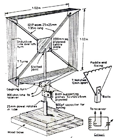
Figure 1: Directional properties of a Loop Antenna
DIY Beverage Antennas
The second key antenna, and probably the best, for MW listeners is the Beverage. This antenna is one of the simplest and oldest designs around, having been developed by Harold Beverage in the 1920s. In fact an antenna of this type, 12km long, was used by Beverage in 1922 for the reception in the USA of some of the first low frequency (approx 1.2 MHz) transmissions from Europe. For a Beverage to be reasonably effective it needs to be between 1 and 10 wavelengths long, which on the MW band implies lengths between 200 and 5000 metres. The longer it is relative to the wavelength of interest, the more directional the antenna becomes. Remember that a Beverage has its maximum signal pick-up along its length and that the antenna should point along the great circle path towards the desired reception area (Figure 2). The Beverage is even cheaper than the loop to build. It is a broadband antenna (i.e untuned) and so effective over the whole MW band, but by virtue of its size it always points in one direction. This means that its reception nulls cannot be easily targeted on unwanted signals. Professional receiving installations (with bigger budgets than DXers) often construct whole arrays of Beverage antennas radiating out like spokes on a wheel from the listening site. The radio monitor of course is able to choose the antenna which gives best quality reception.
Figure 2: Directional properties of a Beverage Antenna
Location
Unfortunately the Beverage is a large antenna but it doesn’t really need much space and it can often be a ‘secret’ antenna erected unobtrusively. Ideally you need to have a large field or woodland at the back of your house but a long straight fence can be used to support the wire. If you have lots of space you have the freedom to chose the beam direction but if you are just taking advantage of local geography then you may have to accept the limitations imposed on you. If you lack any significant space at home a good alternative is to find some open land nearby.Wire
Hard-drawn copper wire is best for a permanent antenna since it won’t break, but it is not cheap and is quite heavy. I tend to use 7/0.2mm multi-stranded insulated wire for temporary DX-pedition type antennas. A continuous barbed wire fence (galvanised steel) is OK also as long as it’s not too rusty to make good electrical connections. If you want to put up a cheap and disguised antenna use thin transformer wire (eg 40 gauge); you can lay this along a hedge row. Whatever wire you chose you’ll need to be prepared for breaks and repairs; ‘chocolate block’ connectors are very useful accessories when working with Beverages.Supports
Gardeners-style bamboo canes (4-6 feet tall) are cheap and good for the job. Just cut a slit at one end with a penknife or junior hacksaw to hold the wire. Lightweight wire (eg 7/0.2mm) needs a support every 15 metres or so. If a straight hedge-row or fence runs in the desired direction you can dispense with the bamboo canes; likewise it is possible to support wire in trees or bushes as long as a reasonably constant height (between 4 and 10 feet) above ground can be maintained.Earth stake and terminating resistor
If a Beverage is operated just as a long wire it will be directional but will pick up signals from both ends of the wire but if the end of the wire furthest from the receiver and nearest the target reception area is terminated with a non-inductive (eg carbon) resistor equal in value to the antenna’s characteristic impedance (usually about 500 – 600 ohms) the antenna becomes unidirectional. For best results it’s good idea to experiment with the resistor value but even a fixed resistor of, say 560 ohms, connected between the antenna and the ground stake will do the job. One good way to produce the terminating resistor is to solder in series a dozen 1 watt 47 ohm resistors which are then encased in either heat -shrink plastic tubing or self-amalgamating tape. The use of many low value resistors makes the whole combination less prone to moisture affecting the total resistance value. Do not forget that for best results a good earth stake is needed at both ends of the antenna, one for the terminating resistor and the other for the receiver.Receiver
If you aren’t operating from a permanent home installation, or planning a full scale DX-pedition from, for example, a farmhouse, you’ll need portable equipment. One good portable receiver that performs very well on the MW band is the Sony ICF2001D. This radio can run off its internal batteries but alternatively a communications receiver that runs off 12V could be used. To make the most of the 2001D (and many other receivers) it is usually essential to place an antenna tuning unit between the Beverage and the radio to avoid overload problems caused by strong local signals. Just imagine the simplicity of driving up to your antenna, parking in a lay-by off the road, and then all that you need to do is pass the antenna wire through the car window, connect it to the receiver and you are ready to go! With a bit of ingenuity you could be DXing with your very own Beverage antenna; you certainly don’t need to own several acres of land. In fact recently I erected a Beverage on a piece of waste land not far from my home. To find the location I did a little browsing of local maps and then surveyed the sites by driving around the neighbourhood. I guess I was lucky but I only had to visit four locations before I found an almost ideal site. Furthermore the site was derelict and deserted so I put up a 330metre run of wire through the bushes. The receiver end terminates on a fence post with some large nails to which I simply connect the receiver with crocodile clips. whilst at the other end I installed the terminating resistor between the antenna wire and a copper earth stake driven deep into soft earth in a ditch. In my case a good ATU is essential since I have a local MW transmitter on 1170kHz.Phasers